Series RC Circuit

Series RC Circuit
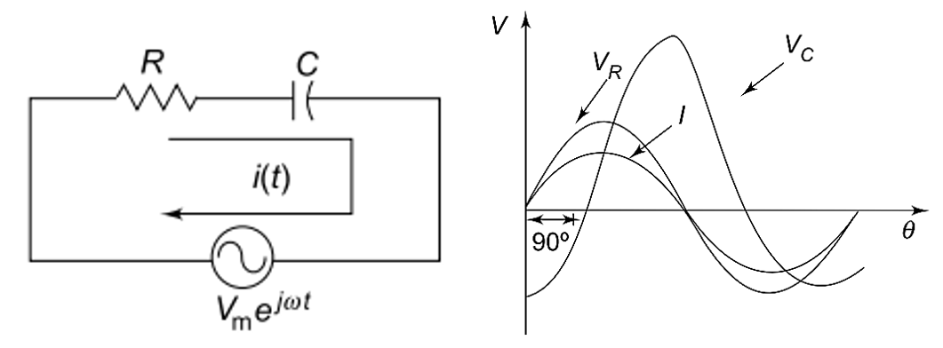
Consider the RC series circuit shown in Fig. 2.14.
If we apply the complex function
to the circuit, we get a complex response.
Applying Kirchhoff’s Voltage Law
Applying Kirchhoff’s law to the circuit, we get:
Solving this equation, we get:
Impedance of Series RC Circuit
Impedance is defined as the ratio of voltage to current.
For a series RC circuit,
where:
Here, impedance consists of:
- Resistance , which is the real part
- Capacitive reactance , which is the imaginary part
The resistance is located on the real axis, and the capacitive reactance is located on the negative axis.
Magnitude of Impedance
The magnitude of impedance is:
Phase Angle
The phase angle is:
Since the circuit is capacitive, current leads voltage.
Phase Relation in Series RC Circuit
When a sinusoidal voltage is applied to an RC series circuit, the current in the circuit and voltages across each of the elements are sinusoidal.
Here:
- The resistor voltage and current are in phase with each other.
- The capacitor voltage lags behind the current by .
- The current leads the source voltage.
The phase angle between the current and capacitor voltage is always:
The amplitudes and phase relations between voltages and current depend on the values of:
- Resistance
- Capacitive reactance
The circuit is a series combination of both resistance and capacitance; therefore, the phase angle between the applied voltage and total current is somewhere between:
depending on the relative values of resistance and reactance.
Voltage Relations
In a series RC circuit, the current is the same through the resistor and capacitor.
The resistor voltage is:
The capacitor voltage is:
Here:
- and are in phase.
- Current leads by .
From Kirchhoff’s Voltage Law, the sum of voltage drops must be equal to the applied voltage.
Therefore, the source voltage is:
Current in Series RC Circuit
The circuit current is:
or
Power Factor of RC Circuit
The power factor is:
Since current leads voltage, the RC circuit has a leading power factor.
Characteristics of Series RC Circuit
- Current leads voltage.
- Impedance has both real and imaginary parts.
- The resistor consumes real power.
- The capacitor stores energy in electric field.
- The phase angle depends on and .
Summary
- A series RC circuit contains resistance and capacitance connected in series.
- The impedance of the circuit is:
- Capacitive reactance is:
- Current leads voltage in a series RC circuit.
- The phase angle is:
- Source voltage is the phasor sum of resistor and capacitor voltages.
More from "Basic Electrical Engineering"
Power in AC Circuits
An introduction to active power, reactive power, apparent power, and power relationships in AC circuits.
Series RLC Circuit
An introduction to series RLC circuits, impedance, phase angle, reactance, and AC circuit behaviour.
Series RL Circuit
An introduction to series RL circuits, impedance, phase angle, phasor relationships, and voltage-current analysis in AC circuits.