Series RL Circuit
Series RL Circuit
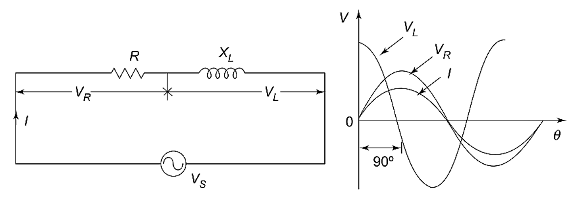
Consider the RL series circuit shown in Fig. 2.13.
If we apply the real function
to the circuit, the response may be
Similarly, if we apply the imaginary function
to the same circuit, the response is
If we apply a complex function, which is a combination of real and imaginary functions, we will get a complex response.
This complex function is:
Applying Kirchhoff’s Voltage Law
Applying Kirchhoff’s law to the circuit shown in Fig. 2.13, we get:
The solution of this differential equation is:
Substituting in the above equation, we get:
Impedance of Series RL Circuit
Impedance is defined as the ratio of the voltage to current function.
Complex impedance is the total opposition offered by the circuit elements to AC current and can be displayed on the complex plane.
The impedance is denoted by .
Here:
- Resistance is the real part of impedance.
- Reactance is the imaginary part of impedance.
The resistance is located on the real axis.
The inductive reactance is located on the positive axis.
The impedance of a series RL circuit is:
where:
Magnitude of Impedance
The magnitude of impedance is:
Phase Angle
The phase angle is:
Current in Series RL Circuit
The circuit current is given by:
or
Phase Relation in Series RL Circuit
In Fig. 2.13:
- The resistor voltage and current are in phase with each other.
- The inductor voltage leads the current by .
- The current lags behind the source voltage .
The phase angle between current and voltage in a pure inductor is always:
The amplitudes of voltages and currents in the circuit are completely dependent on the values of:
- Resistance
- Inductive reactance
In a series RL circuit, the phase angle is somewhere between:
depending on the relative values of and .

Voltage Relations
The voltage across the resistor is:
The voltage across the inductor is:
From Kirchhoff’s Voltage Law, the source voltage is the phasor sum of and .
Thus,
Power Factor of RL Circuit
The power factor is:
Since current lags voltage, the RL circuit has a lagging power factor.
Characteristics of Series RL Circuit
- Current lags voltage.
- Impedance has both real and imaginary parts.
- The resistor consumes real power.
- The inductor stores energy in magnetic field.
- The phase angle depends on and .
Summary
- A series RL circuit contains resistance and inductance connected in series.
- The impedance of the circuit is:
- The inductive reactance is:
- Current lags voltage in a series RL circuit.
- The phase angle is:
- Source voltage is the phasor sum of resistor and inductor voltages.
More from "Basic Electrical Engineering"
Power in AC Circuits
An introduction to active power, reactive power, apparent power, and power relationships in AC circuits.
Series RLC Circuit
An introduction to series RLC circuits, impedance, phase angle, reactance, and AC circuit behaviour.
Series RC Circuit
An introduction to series RC circuits, impedance, phase angle, phasor relationships, and voltage-current analysis in AC circuits.