Mesh Analysis in Electric Circuits
Mesh Analysis in Electric Circuits
Before starting the concept of mesh analysis, we want to reiterate that a closed path or a loop is drawn starting at a node and tracing a path such that we return to the original node without passing an intermediate node more than once.
A mesh is a special case of a loop. A mesh is a loop that does not contain any other loops within it.
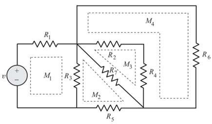
The network shown in Figure has four meshes and they are identified as (M_i), where (i = 1, 2, 3, 4).

Mesh Current
The current flowing in a mesh is defined as mesh current.
As a matter of convention, the mesh currents are assumed to flow in a mesh in the clockwise direction.
Let us consider the two-mesh circuit as shown in Figure.
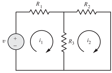
We cannot choose the outer loop as one mesh since it would contain another loop within it.
Let us choose two mesh currents (i_1) and (i_2) as shown in the figure.
Applying Kirchhoff’s Voltage Law
We may employ KVL around each mesh. We will travel around each mesh in the clockwise direction and sum the voltage rises and drops encountered in that mesh.
We will adopt a convention of taking:
- Voltage drops → positive
- Voltage rises → negative
For Mesh 1,
Rearranging,
For Mesh 2,
Rearranging,
Note that when writing voltage across (R_3) in Mesh 1, the current in (R_3) is taken as:
Similarly, in Mesh 2, the current through (R_3) is written as:
Once the mesh currents are known, the branch currents are evaluated in terms of mesh currents and then all branch voltages are found using Ohm’s law.
If we have (N) meshes with (N) mesh currents, we can obtain (N) independent mesh equations.
Solving Mesh Equations Using Cramer’s Rule
The mesh equations can be written in matrix form as:
Step 1: Find the Determinant
The determinant of the coefficient matrix is:
Step 2: Find Determinant for (i_1)
Replace the first column with constants:
Therefore,
Step 3: Find Determinant for (i_2)
Replace the second column with constants:
Therefore,
Summary
- Mesh analysis is based on Kirchhoff’s Voltage Law.
- Mesh currents are generally assumed in clockwise direction.
- A mesh is a loop that does not contain another loop within it.
- Shared branch currents are expressed as the difference of mesh currents.
- Cramer’s rule can be used to solve simultaneous mesh equations systematically.
More from "Basic Electrical Engineering"
Power in AC Circuits
An introduction to active power, reactive power, apparent power, and power relationships in AC circuits.
Series RLC Circuit
An introduction to series RLC circuits, impedance, phase angle, reactance, and AC circuit behaviour.
Series RC Circuit
An introduction to series RC circuits, impedance, phase angle, phasor relationships, and voltage-current analysis in AC circuits.