Series RLC Circuit

Series RLC Circuit
A series RLC circuit is the series combination of:
- Resistance
- Inductance
- Capacitance
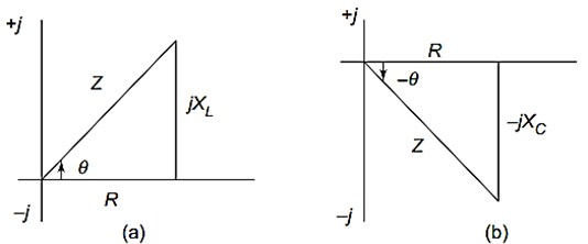
If we observe the impedance diagrams of series RL and series RC circuits as shown in Fig. 2.15(a) and (b):
- The inductive reactance is displayed on the positive axis.
- The capacitive reactance is displayed on the negative axis.
These reactances are apart and tend to cancel each other.
Inductive and Capacitive Reactance
The inductive reactance is:
The capacitive reactance is:
where:
- = inductance
- = capacitance
Net Reactance in Series RLC Circuit
The magnitude and type of reactance in a series RLC circuit is the difference between the two reactances.
Thus,
- If , the circuit behaves inductively.
- If , the circuit behaves capacitively.
- If , the circuit behaves purely resistively.
Impedance of Series RLC Circuit
The impedance of a series RLC circuit is given by:
where:
- = resistance
- = inductive reactance
- = capacitive reactance
Magnitude of Impedance
The magnitude of impedance is:
Phase Angle
The phase angle for a series RLC circuit is:
Current in Series RLC Circuit
The current flowing through the circuit is:
or
Nature of Series RLC Circuit
Inductive Circuit
If
then,
- The circuit behaves inductively.
- Current lags voltage.
Capacitive Circuit
If
then,
- The circuit behaves capacitively.
- Current leads voltage.
Resonance Condition
If
then,
Therefore,
At this condition:
- The circuit behaves like a pure resistor.
- Voltage and current are in phase.
- The impedance becomes minimum.
- The current becomes maximum.
This condition is called resonance.
Voltage Relations in Series RLC Circuit
The resistor voltage is:
The inductor voltage is:
The capacitor voltage is:
The source voltage is the phasor sum of these voltages.
Thus,
Power Factor
The power factor of a series RLC circuit is:
- Lagging for inductive circuits
- Leading for capacitive circuits
- Unity at resonance
Characteristics of Series RLC Circuit
- Contains resistance, inductance, and capacitance in series.
- Reactances oppose each other.
- Circuit may behave inductively or capacitively.
- Impedance depends on net reactance.
- Resonance occurs when .
Summary
- A series RLC circuit contains resistance, inductance, and capacitance connected in series.
- The impedance is:
- The phase angle is:
- Inductive and capacitive reactances oppose each other.
- Resonance occurs when:
- At resonance, impedance is minimum and current is maximum.
More from "Basic Electrical Engineering"
Power in AC Circuits
An introduction to active power, reactive power, apparent power, and power relationships in AC circuits.
Series RC Circuit
An introduction to series RC circuits, impedance, phase angle, phasor relationships, and voltage-current analysis in AC circuits.
Series RL Circuit
An introduction to series RL circuits, impedance, phase angle, phasor relationships, and voltage-current analysis in AC circuits.