Unilateral and Bilateral Networks
Unilateral and Bilateral Networks
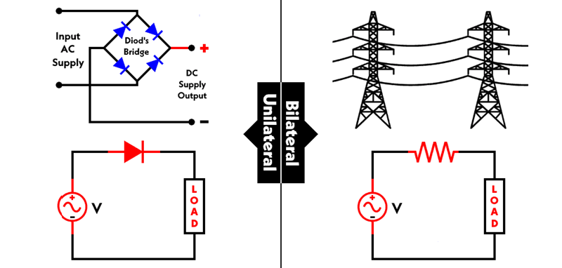
A unilateral network is one whose properties or characteristics change with the direction of signal or power flow. In other words, the network behaves differently when the input and output terminals are interchanged. A common example is the semiconductor diode which conducts current easily in one direction but blocks it in the opposite direction; this directional behaviour makes the diode a unilateral element in many circuit contexts.
Examples of unilateral behaviour:
- Semiconductor diodes used as rectifiers or switches.
- Certain active components and amplifier stages when arranged so that forward and reverse transfer differ significantly.
A bilateral network is one whose properties or characteristics are essentially the same in either direction. Exchanging the input and output terminals does not change the network’s basic response. Many passive, linear two‑terminal elements and networks are bilateral — for example, an ideal resistor, capacitor, or inductor has the same electrical behaviour regardless of direction. A transmission line (under the usual linear, time‑invariant assumptions) is another example: it can carry signals in either direction with the same propagation characteristics.
Examples of bilateral behaviour:
- Passive two‑terminal components: resistors, ideal capacitors, inductors.
- Transmission lines (when linear and reciprocal).
Design note: practical circuits usually contain both unilateral and bilateral elements. Recognizing directionality helps when analysing circuits, choosing matching networks, or designing isolation (e.g., using diodes, circulators, or isolators) where one‑way behaviour is required.
See also: Active circuit elements and sources such as independent and dependent sources, which may interact with unilateral/bilateral components in real circuits.
More from "Basic Electrical Engineering"
Power in AC Circuits
An introduction to active power, reactive power, apparent power, and power relationships in AC circuits.
Series RLC Circuit
An introduction to series RLC circuits, impedance, phase angle, reactance, and AC circuit behaviour.
Series RC Circuit
An introduction to series RC circuits, impedance, phase angle, phasor relationships, and voltage-current analysis in AC circuits.