Norton’s Theorem in Electric Circuits
Norton’s Theorem in Electric Circuits
An American engineer, E.L. Norton at Bell Telephone Laboratories, proposed a theorem similar to Thevenin’s theorem.
Norton’s theorem states that:
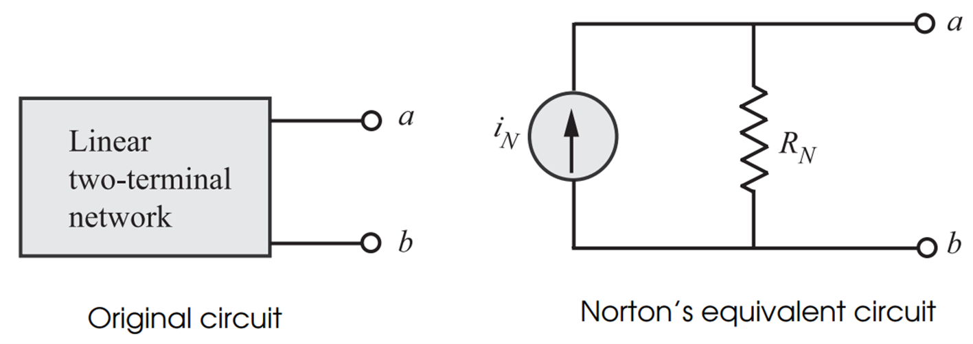
A linear two-terminal network can be replaced by an equivalent circuit consisting of a current source in parallel with a resistor , where is the short-circuit current through the terminals and is the equivalent resistance at the terminals when the independent sources are turned off.
The Norton equivalent circuit consists of:
- Norton current source
- Norton resistance

Norton Current
The Norton current is the short-circuit current flowing through the output terminals.
where:
- = short-circuit current
Norton Resistance
The Norton resistance is the equivalent resistance seen from the terminals after deactivating all independent sources.
Thus, Norton resistance is equal to Thevenin resistance.
Relationship Between Thevenin and Norton Equivalents
In fact, source transformation of the Thevenin equivalent circuit leads to Norton’s equivalent circuit.
The relationship between Thevenin and Norton forms is:
or
Procedure for Finding Norton’s Equivalent Circuit
If the network contains resistors and independent sources, follow the instructions below.
Step 1: Find
Deactivate all independent sources and find the equivalent resistance using circuit reduction techniques.
Source Deactivation
- Independent voltage sources are replaced with short circuits.
- Independent current sources are replaced with open circuits.
Step 2: Find Norton Current
Find the short-circuit current with all sources activated.
Step 3: Draw Norton Equivalent Circuit
Replace the original network with:
- A current source
- A parallel resistance
Reconnect the load resistance to the equivalent circuit.
Load Current Using Norton’s Theorem
If a load resistance is connected across the Norton equivalent circuit, the load current can be determined using current division.
Advantages of Norton’s Theorem
- Simplifies complex circuits.
- Useful in parallel network analysis.
- Makes load current calculations easier.
- Applicable to both AC and DC circuits.
- Convenient for current source networks.
Limitations of Norton’s Theorem
- Applicable only to linear bilateral networks.
- Not directly suitable for non-linear elements.
- Additional calculations may be required for power analysis.
Applications of Norton’s Theorem
- Circuit simplification
- Electrical network analysis
- Electronic circuit design
- Communication systems
- Power system studies
Summary
- Norton’s theorem converts a complex network into an equivalent current source and parallel resistance.
- Norton current is the short-circuit current across the terminals.
- Norton resistance is the equivalent resistance seen from the terminals.
- Norton resistance is equal to Thevenin resistance.
- Source transformation relates Thevenin and Norton equivalents.
- Norton’s theorem simplifies the analysis of electrical circuits.
More from "Basic Electrical Engineering"
Power in AC Circuits
An introduction to active power, reactive power, apparent power, and power relationships in AC circuits.
Series RLC Circuit
An introduction to series RLC circuits, impedance, phase angle, reactance, and AC circuit behaviour.
Series RC Circuit
An introduction to series RC circuits, impedance, phase angle, phasor relationships, and voltage-current analysis in AC circuits.