Thevenin’s Theorem in Electric Circuits

Thevenin’s Theorem in Electric Circuits
The main objective of Thevenin’s theorem is to reduce some portion of a circuit to an equivalent source and a single element.
This reduced equivalent circuit connected to the remaining part of the circuit allows us to find the desired current or voltage easily.
Thevenin’s theorem is based on circuit equivalence. A circuit equivalent to another circuit exhibits identical characteristics at identical terminals.
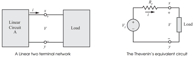
According to Thevenin’s theorem, a linear circuit can be replaced by an equivalent circuit consisting of a voltage source and a series resistance.
The circuit to the left of the terminals is known as the Thevenin equivalent circuit.
Statement of Thevenin’s Theorem
Thevenin’s theorem may be stated as follows:
A linear two-terminal circuit can be replaced by an equivalent circuit consisting of a voltage source in series with a resistor , where is the open-circuit voltage at the terminals and is the equivalent resistance at the terminals when the independent sources are turned off.
The equivalent circuit consists of:
- Thevenin voltage
- Thevenin resistance
Thevenin Voltage
The Thevenin voltage is the open-circuit voltage measured across the terminals.
where:
- = open-circuit voltage
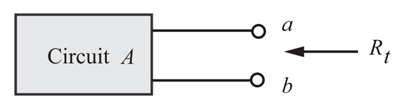
Thevenin Resistance
The Thevenin resistance is the equivalent resistance seen from the terminals after removing all independent sources.
Action Plan for Using Thevenin’s Theorem
Step 1: Divide the Circuit
Divide the original circuit into:
- Circuit A
- Circuit B
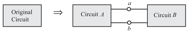
In general:
- Circuit B is the load which may be linear or non-linear.
- Circuit A is the remaining part of the network exclusive of the load and must be linear.
Circuit A may contain:
- Independent sources
- Dependent sources
- Resistors or other linear elements
Step 2: Separate the Load
Separate circuit B from the original circuit.
Step 3: Replace Circuit A
Replace circuit A with its Thevenin equivalent consisting of:
- A voltage source
- A series resistance
Step 4: Reconnect the Load
Reconnect circuit B and determine the required quantity such as:
- Load current
- Load voltage
Procedure for Finding
If the circuit contains only independent sources and resistors:
- Deactivate all independent sources.
- Find the equivalent resistance seen from the open terminals using circuit reduction techniques.
Source Deactivation
- Independent voltage sources are deactivated by replacing them with short circuits.
- Independent current sources are deactivated by replacing them with open circuits.
Procedure for Applying Thevenin’s Theorem
- Remove the load resistor from the circuit.
- Calculate the open-circuit voltage across the load terminals.
- Deactivate all independent sources.
- Determine the equivalent resistance seen from the terminals.
- Draw the Thevenin equivalent circuit.
- Reconnect the load resistor.
- Calculate the required current or voltage using Ohm’s law.
Current Through Load Resistance
If a load resistance is connected to the Thevenin equivalent circuit, the load current is:
Voltage Across Load Resistance
The voltage across the load resistance is:
Substituting the value of ,
Advantages of Thevenin’s Theorem
- Simplifies complex circuits.
- Reduces repeated calculations.
- Useful in load analysis.
- Helps in studying the effect of varying load resistance.
- Applicable to both AC and DC circuits.
Limitations of Thevenin’s Theorem
- Applicable only to linear bilateral networks.
- Not suitable for non-linear elements directly.
- Power calculations require additional computations.
Applications of Thevenin’s Theorem
- Circuit simplification
- Load current analysis
- Power system studies
- Electronic circuit design
- Communication circuits
Summary
- Thevenin’s theorem converts a complex network into a simple voltage source and series resistance.
- Thevenin voltage is the open-circuit voltage across the terminals.
- Thevenin resistance is the equivalent resistance seen from the terminals.
- Independent voltage sources are replaced by short circuits during resistance calculation.
- Independent current sources are replaced by open circuits.
- The theorem greatly simplifies circuit analysis and load calculations.
More from "Basic Electrical Engineering"
Power in AC Circuits
An introduction to active power, reactive power, apparent power, and power relationships in AC circuits.
Series RLC Circuit
An introduction to series RLC circuits, impedance, phase angle, reactance, and AC circuit behaviour.
Series RC Circuit
An introduction to series RC circuits, impedance, phase angle, phasor relationships, and voltage-current analysis in AC circuits.